TECAPOWDER PI HCM grades are used to make high performance polyimide stock shapes and finished parts. They are heat aged in vacuum so that high quality stock shapes can be molded without the need for post curing. Large billets can be molded without cracking. HCM grades are available unreinforced, or with fillers such as graphite powder for compression molding, or ram-extrusion into stock shapes or direct formed into finished parts.
TECAPOWDER PI is a fully imidized polyimide with no need for post curing (based on P84® by Evonik).
Excellent thermal resistance makes TECAPOWDER PI HCM parts useful in many markets. Depending on the fillers, the outstanding properties can be customised to suit the application.
TECAPOWDER PI HCM grades are available in virgin grades and blended grades, custom formulations can be readily made.
TECAPOWDER PI HCM blends contain various fillers based on the end use application. Graphite filled grades are excellent for bearings or bushings that require high wear resistance, often without lubrication. Glass filled TECAPOWDER PI HCM is useful in the metal spinning industry. Rollers made with glass fiber filled TECAPOWDER PI HCM produce a smooth finish on metal parts.
All TECAPOWDER PI compounds are widely available and custom formulations can be readily made.
Hot compression moulding is the sintering of the material at temperatures above the glass transition temperature under a pressure of 35 MPa (5,000 psi). Molding temperature is 350 °C (662 °F). The necessary equipment is a press which is able to maintain 100 metric tons over a 15 hour cycle, and a top and bottom heated mould with heater-band.
Example: the production of a 20 cm (8 in) diameter 5 cm (2 in) high billet.
A suitable release agent is recommended. Before filling the mold, the powder must be dried to eliminate the equilibrium moisture. Drying can be done at 100 °C (219 °F) over 2 hours for a 1.8 kg (4 lb.) loading. At the filling step, the mould should be preheated to 250 °C (480 °F) and the powder should be transferred directly out of the oven into the mould. The first compression up to 17 MPa (2,500 psi) should remove the air from the loading. After this step the heating starts with a ramp up to 300 °C (572 °F). At this temperature the first dwell time with 1 hour is necessary. Then the full pressure of 35 MPa (5,000 psi) is applied and the ramp up to 340 °C (647 °F) starts.
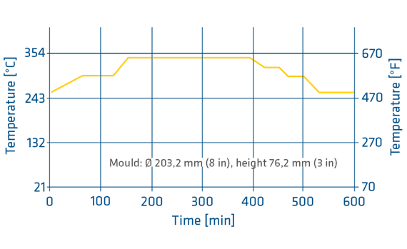
Reaching this temperature, a dwell time of 4 hours is needed to get uniform heat penetration. At the end of this program a slow cooling ramp starts to reduce temperature within 4 hours down to 250 °C (480 °F) under the full pressure. After reaching this temperature the part should be released.
Graphite
Ensinger tested most available graphite types to choose the best material for TECAPOWDER PI. The following properties are significant for use:
PTFE
To get a uniform matrix and best friction and wear properties the use of very fine PTFE particles is necessary. Also, the melting point of the additive material should be at the same level as the matrix materials Tg.
MoS2
The lubrication of MoS2 is based on surface-smoothing through material transfer. In this respect it is very important to have very fine particles as a filler and the right percentage in composition. For being able to process MoS2 at approximately 345 °C (650 °F) Ensinger offers a special grade of TECAPOWDER PI.
When machining TECAPOWDER PI the following rules should be adhered to:
P84 parts machine easily using standard turning equipment. It is recommended to use carbide-tipped tools. For rough and finish turning operations use a cutting geometry similar to that used for aluminum, for turning on a numerically controlled lathe. The nose radius of the cutting tip should be between 0,1 and 0,2 mm (0,004 and 0,008 in) to guarantee a good surface finish. It is important the cutting tip be level to the center of the piece to be turned. Sharp cutting edges allow high cutting speeds use low feed rates.

P84 parts can be ground to close tolerances with surface grinders used for metal working. Round bars and tubes are ground on centerless grinders. Use double-coated tape to fix the material to the table and cool with water. Table surface speed should be about 0,3 m/s (60 ft/min) for rough grinding and 0,18 m/s (35 ft/min) for finish grinding.
| Cutting Speed |
Feed |
||
| feed/min | mm/R | in/R | |
| Rough turning | 300-450 | 0,25-0,5 |
0,01-0,02 |
| Finish turning | 450-550 | 0,05-0,15 | 0,002-0,006 |
| Parting | 240-300 |
0,05-0,08 |
0,002-0,003 |
TECAPOWDER P84 parts can be machined with all standard HSS or carbide-tipped milling equipment. Multiple-point milling cutters are preferably used. To avoid edge chipping, we recommend the milling be performed from the outside of the block towards the center and use small exit angles. Cutting speed should be between 6,35 and 10 cm/min (2,5 and 4 in/min) and feed rates lower than 0,7-0,15 mm (0,03-0,006 in). The lower the feed rate, the better the surface finish. Lubricating or cooling is not required.

SS drills (point angle 90 °C) or carbide drills (point angle 90-120 °C) can be used to drill holes into P84 parts. If the drill diameter is more than 2 cm (0.8 in), reduce the web thickness. Work at drilling speeds of 2,3-2,8 m/s (450-550 ft/min) and feed rates lower than (0.004 in). To avoid local heating in the workpiece, provide for good chip removal.
TECAPOWDER P84 materials can be cut with circular or band saws. If you use hard metal tipped blades, tool life will be longer. Saw speed for circular saws should be 2-3 m (80-120 in), for band saws 0,3-0,4 m (12-16 in). If plates are to be cut with circular saws, adjust the blade height in such a way that the blade breakthrough is within 2-3 mm (0,08-0,12 in) to the surface to avoid edge chipping.
This process is used to make smaller stock shapes of TECAPOWDER PI resins. The diameters are limited by the handling possibilities of the moulds. Common mould sizes have outside diameters of 20-25 cm (8-10 in). The moulds have to be able to maintain pressures up to 69 MPa (10.000 psi) at 400 °C (752 °F). This indicates the use of high wall thicknesses and hot working steels to be used for the tools. Sintering can be done in a simple air circulation furnace which can maintain temperatures up to 400 °C (572 °F).
The following steps will describe how to mould and sinter during this process.
The calculation for the sintering time (dwell time) should be approximately 1.5 hours/2.5 cm (1 in) wall thickness.
For further information, please contact: [obfemailstart]dGVjYXBvd2RlckBlbnNpbmdlcnBsYXN0aWNzLmNvbQ==[obfemailend]